
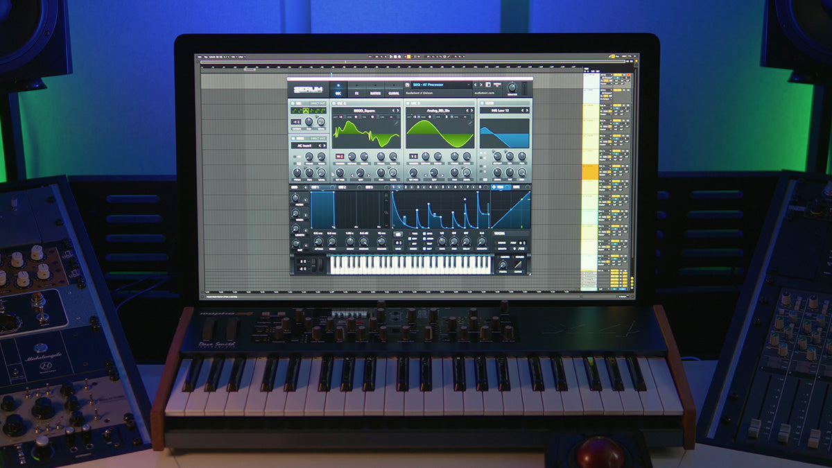
Welcome! In this step-by-step tutorial, we will deconstruct 1 of the 107 presets included in the Audiotent - Nemesis (Arturia ARP 2600) preset library.
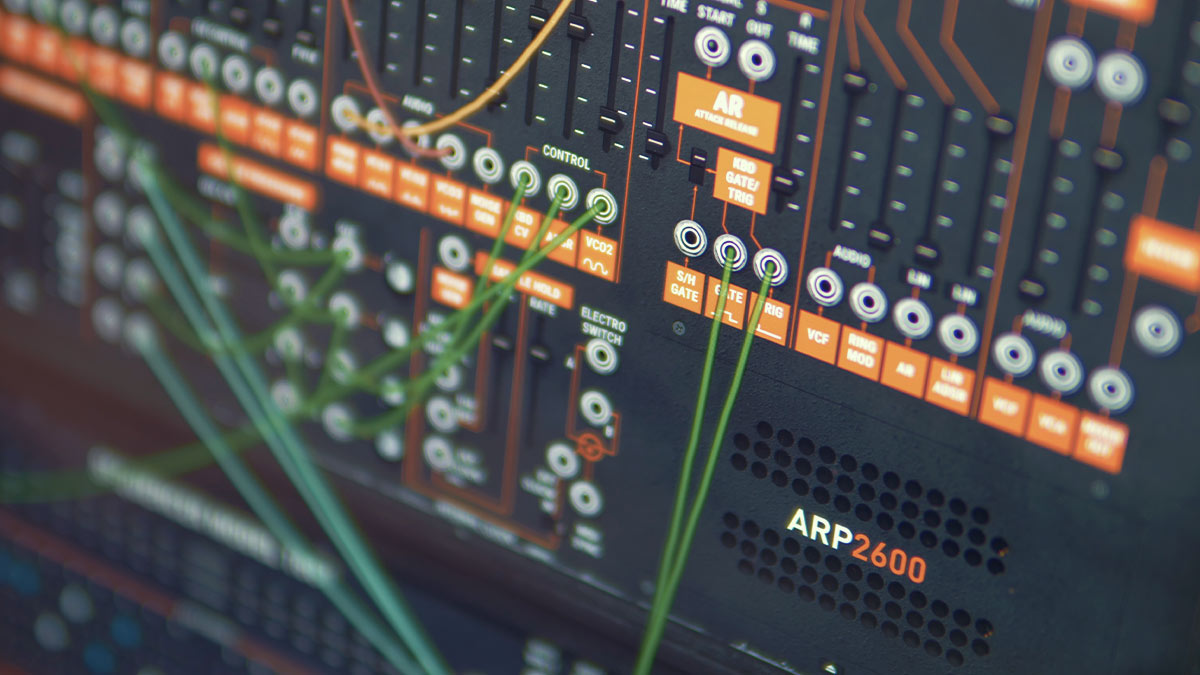
As you will discover, the bass preset has a fairly complex routing layout. Don't worry, all will be explained in detail. We promise you will have a much deeper understanding of the voltage processor and clock outputs by the end of the guide.
One thought to take away from all of this is the amount of time it takes to create some of the more complex patches. If you don't want to end up spending hours designing a sound, presets can be a huge time saver! This allows you to focus your energy on music production and get more tracks completed.
Note:
- Modulation sources are highlighted with a red circle.
- Destinations are highlighted with a green circle.
- Key points are highlighted with a blue arrow or blue square.
- Bonus tips to try out in your productions will be given in italics.
AT Bass - Grinds is a sawtooth bass patch with a thick analog tone and a punchy but deep shape, it works especially well for melodic bass lines. The four macros and modwheel can be used to quickly add dynamic opening and closing of the sound. Let's look into how the patch was constructed, starting with the oscillators.
To generate the basic sound source for this patch, we are using the Saw waveform generated by VCO (Voltage Controlled Oscillator) 1. Instead of patching one cable from VCO1 Saw to the VCF (Voltage Controlled Filter) Audio Mixer, we are patching three instances using three cables, patched into three audio mixer inputs. By doing this we are increasing the overall volume, driving the circuitry of the VCF and VCA (Voltage Controlled Amplifier), which adds subtle saturation and warmth. The levels of these 3 inputs are increased using the Sliders above the inputs.

Next, a more pleasing timbre is dialled in using subtle FM modulation. VCO2 is not audible but it is been used as the modulation source to modulate the frequency of VCO1, the modulation amount is increased using the Slider highlighted below. Also take note of VCO2 settings, the pitch is the same as VCO1 with some detuning by offsetting Fine Tune.
You can hear more intense frequency modulation by increasing VCO1 octave and increasing the depth amount using the Slider highlighted.

Using FM Modulation has caused the pitch of VCO1 to be offset, to counterbalance this we need to decrease the Global Tune by -71.78%

To finish off the initial sound generation, we also added a subtle touch of white noise into the signal by increasing Noise Generator Level on the VCF Mixer. This is a simple way to add a little organic grit and character into a synth patch.

Next, let's take a look at the VCF (filter) section, the filter is set to 24db Low Pass with no resonance and we have 3 modulations affecting the position of the filter cutoff.
Try playing around with filter frequency and maybe increasing the resonance a little.
The three modulation sources affecting the cutoff position are Keyboard CV, AR Envelope and VCO2.
Before we look closely at these 3 modulation sources and routings, try bringing the 3 depth sliders highlighted below down, and then increase each one individually to get an idea of how they are shaping the opening and closing of the filter cutoff.
The first slider, Keyboard CV opens the filter cutoff more as higher notes are played, allowing higher frequencies to come through more when needed. Without this higher notes may sound fairly dull.
The second slider is usually ADSR (Attack Decay Sustain Release) Envelope, but in this patch we are bypassing the ADSR routing and patching in CV from the AR (Attack Release) Envelope. More on how this was set up in a second.
The third slider brings in modulation from VCO2, the same modulation source we used to modulate VCO1 frequency. This is a trick used to subtly adjust the timbre by modulating the cutoff position at a high rate.

Let's take a step back and look into the AR Envelope routing in more detail. To re-trigger the AR Envelope we are using the Sequencer Model 1601, the sequencer starts with every key press, Start and Reset CV’s are patched in replacing Gate and Trig. We are also taking CV from Clocked Gate Out, patching into Voltage Processor 4 and then back Out into AR replacing SH Gate connection. Don't worry too much about understanding the reasons for using Voltage Processor, we will dive into that later on.
A little more on how we have Clocked Gate Out set up. On the sequencer gate buss switches you will notice that all switches are set to the middle point which is Gate Buss 2, apart from the first one which is set to Gate Buss 1. Gate Buss 1 sends a control voltage to Clocked Gate Out every time the sequencer lands on that first step, meaning every time we hit a note, the sequencer starts, sending a signal to Clocked Gate Out and re-triggering the AR Envelope. It seems like a complex solution for a basic operation but reasons will become apparent as we start to look at modulation routings via the mod wheel later on.
So now, we are re-triggering the AR Envelope, we need to send the AR Envelope CV to VCF Control. To do this we have connected AR Out to Voltage Processor 2 and then Out to VCF Control, replacing the ADSR connection.
Have a play around with the Attack and Release times, notice how the shape of the modulation changes.

You may have noticed the cable connecting AR Re-trig to ADSR Re-trig, this is sending the sequencer Start CV also to ADSR Envelope to re-trigger the envelope. ADSR in this patch is used to shape the VCA (Voltage Controlled Amplifier) The depth amount for this is brought up using the highlighted slider in the VCA section.

Now we have looked at the basic setup of this patch let's take a closer look at FX and Modulation.
For effects we have a Spring Reverb and Delay combination but set up in a unique and unconventional way. You may have noticed that Spring Reverb is only present on the left output and Delay only on the right output. Let’s take a look at how this is set up.
For the Spring Reverb only the Left Slider is opened up and the Right Slider is all the way down. For the Delay, Dry/Wet for the stereo signal is open but Left Time is all the way down and Right Time is set to Tempo (whole note). The Left Feedback is also all the way down, and Right Feedback is set to 0.30, these settings sound like the Delay is only present on the right output. The combination of the Delay and Reverb settings makes for an interesting stereo layer behind the main sound.
Try adjusting the Delay Time to fit the groove of your sequence, and adjusting Feedback amount. You could also make both effects stereo if you wish by opening up the Right Reverb slider and Left Delay Time and Feedback.

Next, we will look at the modulation that is enabled via the Modwheel. Try opening up the Modwheel on a midi keyboard.
There is quite a lot going on here in terms of patching so let's unpack this systematically bit by bit.
First, we will look at how the Modwheel speeds up the Sequencer Clock, creating a high rate LFO type of effect by re-triggering the AR Envelope at a faster rate. Modwheel CV is patched into Voltage Processor 7, Link is enabled so that 7 is mixed in with Voltage Processor 5 and 6 (the row above). This signal is sent Out of Row 3 and into Clock FM, as you increase the Modwheel amount it will speed up the Sequencer Clock.
Initially we are using Clocked Gate Out and we need to switch to Clock Out to hear the clock speeding up. Clock Out is patched into Voltage Processor 3 but the Mix Slider is all the way to the right, allowing just Voltage processor 4 (Clocked Gate Out) to be sent to AR Envelope. What we want is for the Mix Slider to move to the left when we open up the Modwheel, switching over to Clock Out, which will allow for faster rates. For this to happen, we have patched Mod Wheel CV to Row 2 Mod In, which modulates the Mix Position, and pushed the Depth Amount (orange ring) to the right.

We still need to look into how the LFO is operating within this patch. Modwheel CV is also patched into LFO Mod In, with the Depth Amount turned clockwise to around 5’o’clock. As the Modwheel is opened, the LFO Depth Amount is increased. The LFO is Midi Synced to host clock (DAW clock) and set to Tempo 4.0 LFO Speed.
Next, the Triangle LFO is patched to Voltage Processor 5, but like the row above the Mix Slider is all the way to the right just letting the Modwheel opening up Clock FM amount. For the LFO to be mixed with Modwheel CV, which is been sent to Clock FM, we need to bring the Mix Slider to the left a little as we open up the Modwheel, this is achieved by sending Modwheel CV to Row 3 Mod In, with the Depth Amount clockwise around 2:30.

Triangle LFO is also been sent to Row 1 Mod In, with the Depth Amount set to 10’oclock. This is to modulate the Mix Slider when we open the Mod Wheel, adding more AR Envelope Depth Amount for the VCF.

Sound design is a never-ending learning experience. We encourage you to reverse engineer presets that you find interesting. This will enable you to build up your synthesis techniques and apply them when developing your own sound.
This preset that we covered today is just a fraction of what is included inside the full Nemesis preset library: https://www.audiotent.com/presets/nemesis/
Leave a comment
This site is protected by hCaptcha and the hCaptcha Privacy Policy and Terms of Service apply.